Compatibility of CAN and CAN FD
In automotive applications, customers often ask about the compatibility of CAN and CAN-FD. Although CAN 2.0 and CAN FD are extensions of the same standard, there is often a misconception that the two are not compatible. CAN FD allows for a different data length and the potential for faster bit rate than CAN 2.0; however, CAN FD and CAN 2.0 devices may be used in the same network. This post provides a quick introduction to the protocol differences and compatibility.
Background
The CAN (Controller Area Networking) bus was defined in the late 1980s by Bosch, initially for use in automotive applications (CAN 2.0). In 2014, an enhancement to the spec (CAN FD) was developed to improve throughput. CAN is a multi-master protocol that uses a single terminated twisted pair cable. The maximum bit rate available is 1 Mbit/sec (CAN 2.0) and 12 Mbit/sec (CAN FD).
CAN is attractive for automotive networks because of its high reliability. Nodes on the network are not assigned addresses; rather, the messages themselves have an identifier which also determines the message priority. No two nodes can transmit the same message identifier because this would violate priority rules. In general practice, no more than 64 nodes can be on a single bus, though theoretically there is no limit. The data to define message details is typically maintained in a calibration table within a subsection of the firmware which can be updated without requiring a full firmware update. The industry standard to test CAN messages/routing is to create DataBase CAN (DBC) files (Vector proprietary format) for each node on the network.
Message Structure
The CAN protocol uses a modified version of the Carrier Sense Multiple Access/Collision Avoidance (CSMA/CA) technique used on Ethernet. Should two messages determine that they are both trying to send at the same time, instead of both backing off and re-trying later (as is done with Ethernet), the CAN physical circuitry (PHY) detects which message has the highest priority and the lower priority message gets delayed. This means that a high priority message will always get through. The detail of how this occurs is handled by the PHY, and is not applicable to this overview. It is only of interest to those designing controllers, but details can be found in ISO 11898.
The basic message structure, which is the same for both CAN 2.0 and CAN FD, is shown below: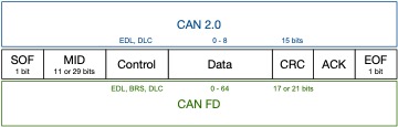
For CAN 2.0 all bits are sent at the speed setting for the bus up to 1MBits/sec with the following fields:
- Start of frame (SOF).
- Message Identifier (MID) where the Lower the value the Higher the priority of the message. The length is either 11 or 29 bits long depending on the standard being used (Standard or Extended).
- Remote Transmission Request follows MID. Always = 0 in many applications; therefore omitted above.
- Control field which contains an EDL to differentiate between CAN 2.0 or FD transaction and a DLC to specify the number of bytes of data to follow (0-8 for 2.0).
- Data Field length 0 to 8 bytes for CAN 2.0.
- Cyclic Redundancy Check (CRC)
- Acknowledge field (ACK) is an empty slot which will be filled by every node that receives the frame. This does not acknowledge the data was received by the intended node, rather it means at least one node on the whole network received it.
- End of Frame (EOF).
For CAN FD all bits are sent at the speed setting for the bus up to 12MBit/sec with the same fields as described for CAN 2.0 except the CRC is longer and the control field contains:
- an EDL to differentiate between CAN 2.0 or FD transaction
- a bit rate switch (BRS) where 0 = no change in bit rate for the data phase and 1 = change to the nominated higher bit rate
- a DLC to specify the number of bytes of data to follow (0-8, 12, 16, 20, 24, 32, 48 or 64)
The table below provides a comparison of these details between CAN 2.0 and CAN FD.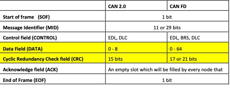
Message collision is avoided because the PHY on each node that transmits its MID looks on the bus to see what other nodes are seeing. If an MID is in conflict with a higher priority MID (lower number), the higher priority message bit will pull the signal down (a zero bit is called dominant) and the lower priority node will stop transmitting.
CAN 2.0 and CAN FD Are Compatible, Not Interchangeable
A CAN 2.0 message can be transmitted directly on a CAN FD bus without changes to the format since CAN FD is backward-compatible with CAN 2.0. Of course, CAN 2.0 messages must be added to the CAN FD DBC file (for test cases) or CAN FD calibration table (for industry releases) with correct message structure, and the CAN FD PHY must be configured to CAN 2.0 mode on all FD nodes within the same bus. A CAN FD bus cannot support CAN 2.0 and CAN FD messages at the same time.
A CAN FD message can be “converted” to CAN 2.0 with few changes if the message data is 8 bytes or less. The message(s) must be added to the appropriate files with correct message structure and timing, as described above.
Converting a CAN FD message when the message data is greater than 8 bytes is very unlikely aside from a test or simulation scenario. This is because with a larger data size in the message, there is no reason to separate the data and slow the message down. If, for some reason this is desired, interface repackaging is required and can be performed in firmware using Transport Protocol (ISO 15765-2). All CAN FD timeouts need to respect the CAN 2.0 calibration table.
In the case of converting messages for a test or simulation, such as when a CAN FD physical interface must be tested without a second CAN FD interface, it’s possible to reconstruct the message into several CAN 2.0 messages and create timing changes in the DBC files.
For a more detailed explanation of the message structure, refer to our complete introduction document. For more detail about CAN 2.0 and CAN FD, ISO 11898-1 defines the data link layer, ISO 11898-2 defines the high-speed physical layer, and ISO 11898-3 defines the low-speed physical layer. Refer to ISOs released 2015 or later to ensure accurate CAN FD details are included.